| |
|
1. |
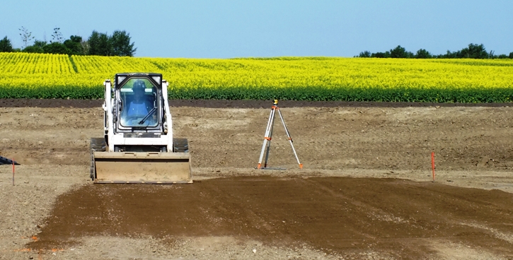
Clear and level area
(transit level) required to place properly
and set-up secondary containment system. |
|
| |
|
|
|
|
| |
|
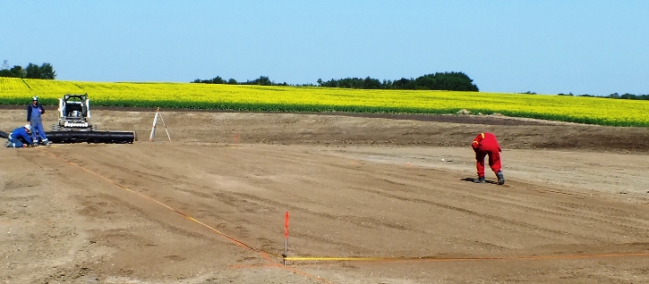
2. |
Mark out containment area
berm with paint or stakes to determine
actual placement or foot print of the containment wall
package. |
|
| |
|
|
|
|
| |
|
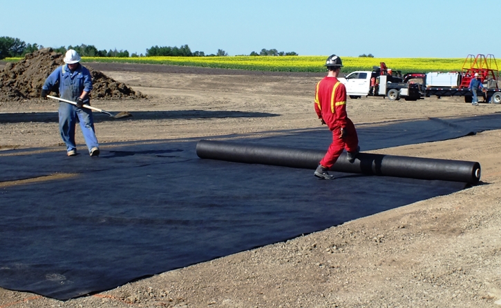
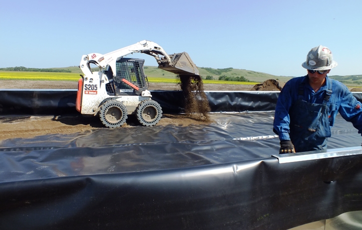
3. |
Place 2" - 6" of
screen sand (wash sand) or
non-woven geotextile over containment
ground area to protect liner. Sand
depth is dependent on ground conditions (clay,
top soil, rocky, etc.) and whether or not geotextile will be laid under liner as
well as
liner thickness. |
|
| |
|
|
|
|
| |
|
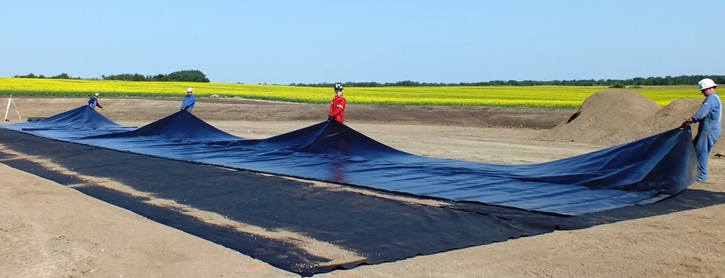
4. |
Carefully unfold liner
ensuring it is wrinkle free and
centered in the containment area on sand or
geotextile. |
|
| |
|
|
|
|
| |
|
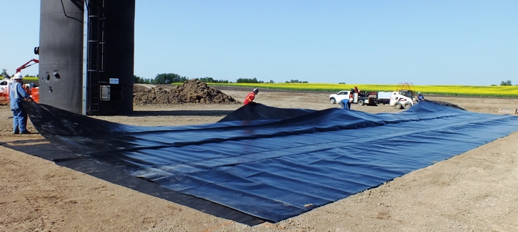
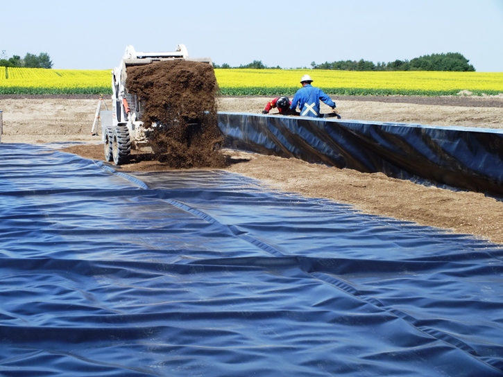
5. |
Place 2" - 6" of
screen sand and
non-woven geotextile if required over containment
liner for protection leaving approximately 3'
of uncovered
liner around the perimeter of the
containment wall. Fold liner
inward to ensure it does not get damaged
while setting up the wall panels. |
|
| |
|
|
|
|
| |
|
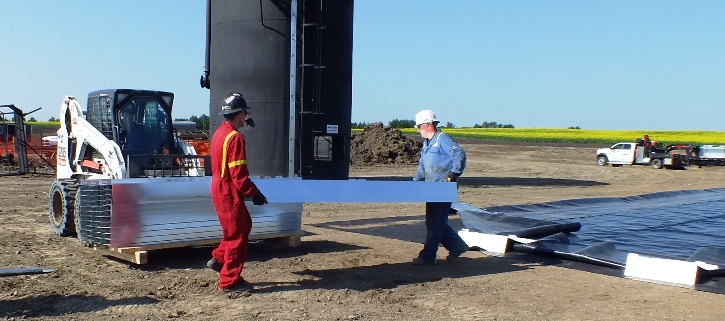
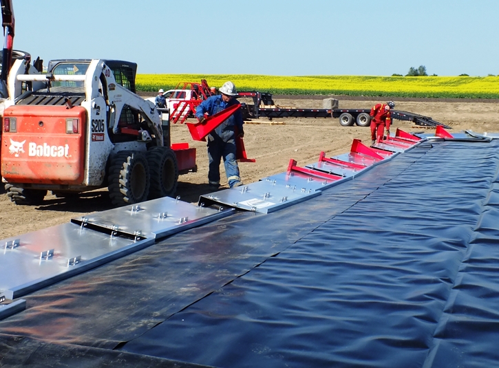
6. |
Place the steel
containment wall panels face down around the
perimeter of where the berm will stand.
Place the panels in such a way that when the
wall is setup, the outside of the panel will
be directly on the actual berm foot print as
marked. |
|
| |
|
|
|
|
| |
|
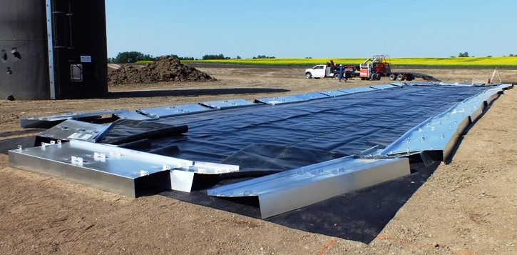
7. |
While the panels are face
down, slide each of the legs into the
wall clips until the top of the leg reaches
the top of the wall. |
|
| |
|
|
|
|
| |
|
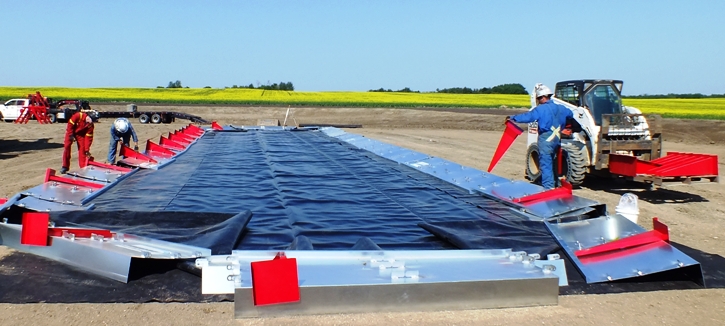
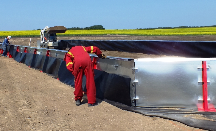
8. |
Stand the panels up
carefully, ensuring the legs do not slide
out and the outside of the panel is in line
with the berm foot print as marked. |
|
| |
|
|
|
|
| |
|
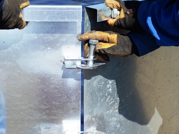
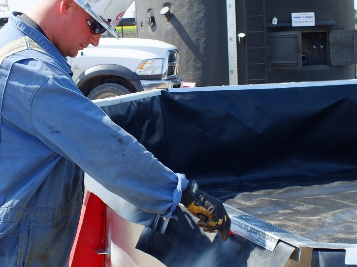
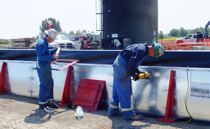
9. |
Connect all adjoining
panels with 3 locking drop pins. |
|
| |
|
|
|
|
| |
|
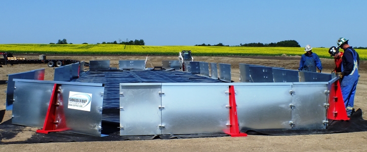
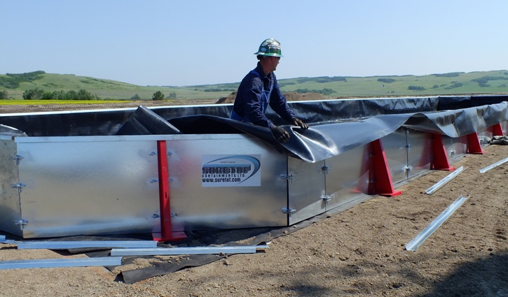
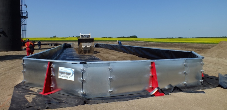
10. |
Continue around the
perimeter until the entire system is erected
and square. |
|
| |
|
|
|
|
| |
|
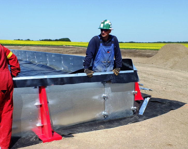
11. |
Fold liner towards wall
panels
ensuring it falls into corners with a loose
fit. Minimize folds and creases. |
|
| |
|
|
|
|
| |
|
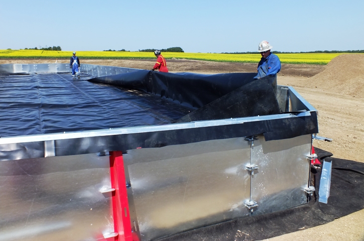
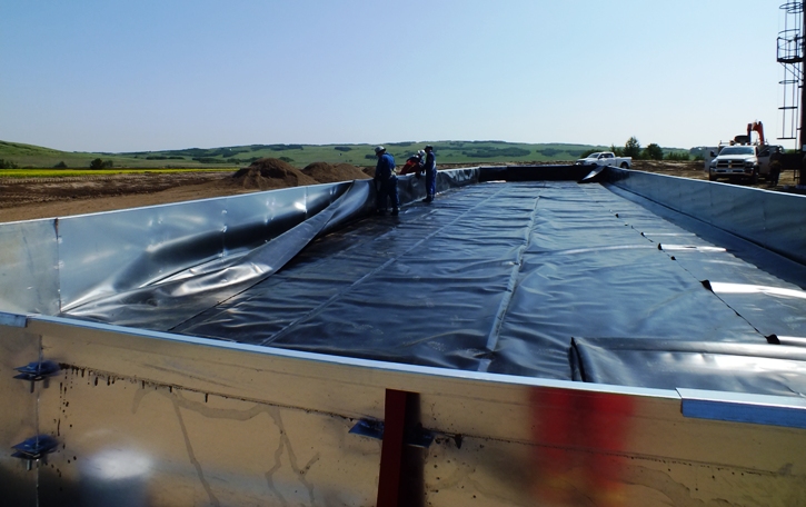
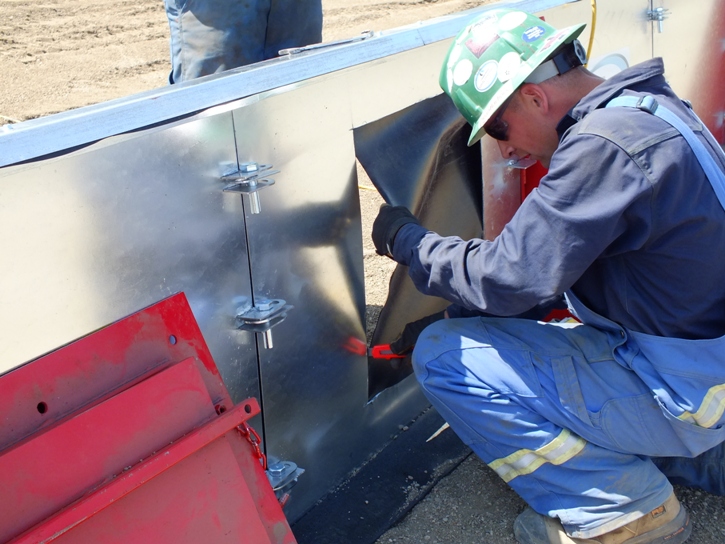
12. |
Take liner up and over
the berm walls. The corners will
require extra attention - they will have to
be carefully folded compared to wrapping a present. |
|
| |
|
|
|
|
| |
|
13. |
Take corner top ridge
caps, two (2) – 4’-3” pieces, and place 90o
of each other and secure to the top of the
wall using six (6) Hex Tek self-tapping
screws, three (3) screws per corner piece.
This will secure the liner in each corner
once the liner has been folded properly. |
|
| |
|
|
|
|
| |
|
14. |
Fasten the 8’-0” top
ridge cap pieces to the top of the wall
using four (4) Hex Tek self-tapping screws
to secure the liner. Start from the corner
ridge cap pieces outward. Custom size
walls will require the top ridge cap to be
field cut to fit properly. Cut ridge caps
in such a manner the caps overlap the
wall seams by no less than 2 feet. |
|
| |
|
|
|
|
| |
|
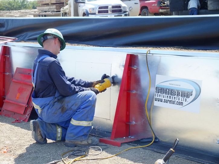
15. |
Trim extra liner around
exterior of ridge cap to ensure a neat
appearance. |
|
| |
|
|
|
|
| |
|
Tools
Required: |
|
| |
|
 |
Cut-off Saw |
|
| |
|
|
Cordless Drill |
|
| |
|
|
3/8" Nut Driver to fit
drill (for self-tapping
screws) |
|
| |
|
|
Utility Knife |
|
| |
|
|
Shovel & Rake |
|
| |
|
|
|
|
| |
|
C.O.R.
Certified: |
|
| |
|
 |
C.O.R. Certified installation
crews |
|
| |
|
|
Are the approved vendor for most
major companies |
|
| |
|
|
Workers have ALL required
safety tickets and safety equipment |
|
| |
|
|
F-550 Picker equipped, 4x4, SuperCrew,
complete with 30' 5th wheel trailer, bobcat, transit,
tamper, etc. |
|
| |
|
|
NO OVERTIME / NO FUEL SURCHARGE / NO
SHOP OR MISCELLANEOUS CHARGES |
|